


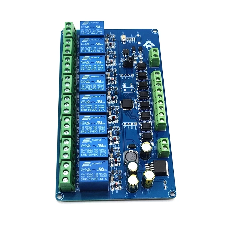
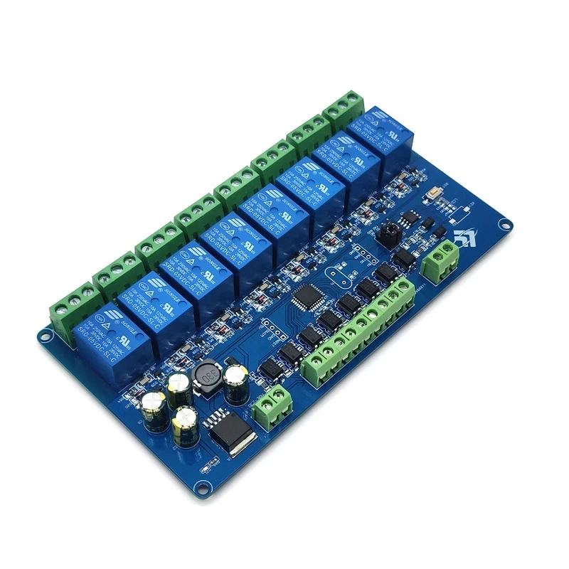
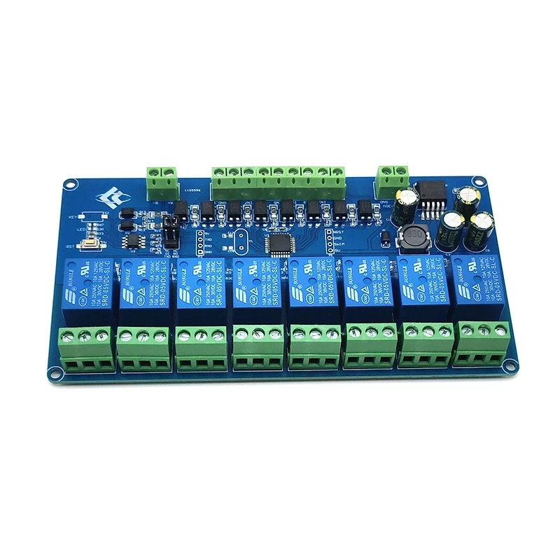
Modbus RTU 8ch relay module RS485/TTL UART 8CH input 8CH out
SKU :LC-Modbus-8R-D7
Overview
LC 8 channel Modbus relay module equipped with mature and stable 8-bit MCU and RS485 level communication chip,adopt standard MODBUS RTU format RS485 communication protocol ,It can realize 8 channel optocoupler input signal detection and 8 channel relay output, can be used for digital detection or power control occasions.
Functions:
1.Onboard mature and stable STM8S103K3T6 MCU and MAX485 level communication chip.
2.Communication protocol:support standard Modbus RTU protocol
3. Communication Interface:support RS485/5V Level TTL UART interface
4.Communication baud rate: 4800/9600/19200,default 9600bps, Support power-down save.
5.Optocoupler input signal range, DC3.3-30V(this input not available for relay control)
6.Output signal:relay switch signal, support manual control,flash OFF/ON mode,The delay base is 0.1S,the maximum allowable flash OFF/ON time is 0xFFFF*0.1S=65535*0.1S=6553.5S
7.Device address:range:1-255,default 255,Support power-down save
8.Baud rate/optocoupler input status/relay status/device address can be read by software/commands.
9.On-board 8 channel 5V,10A/250V AC 10A/30V DC relay,can continuously sucking 100,000 times, it has Diode flow protection for short response times.
10. On-board relay switch indicator.
11. reserve STM8 SWIM programming port, support customers' secondary development to download their own firmware
12.supply voltage:DC7-30V, adopt 5.08mm terminal power supply.
Introduced the hardware and instructions
1.board size:143*79.8 (not include case) weight :145g(not include case)
1,VCC,GND:DC7-30V 5.08mm power input terminal
2,DC3.3-30V Optocoupler signal input
IN1-IN8: channel 1-channel 8 positive
GND_IN:channel 1-channel 8 Common negative
3, A+,B-:RS485 communication Interface, A+, B- are respectively connected to A+, B- of the external control terminal.
4,5V,SWIM,GND,NRST:STM8 SWIM program download port.
5,TXD,RXD,GND:TTL level UART Communication Interface,TXD,RXD,GND respectively connected to the external control terminal RXD,TXD,GND,only support 5V level TTL module /MCU. Recommended wiring sequence :Modbus module power on - Modbus module connect TTL module -TTL module power on .
6,RST: MCU reset button
7,Relay switch signal output
NO:normally opened end,the NO disconnect with COM when relay released and connect with COM when relay closed.
COM: common end
NC:Normally closed end ,the NC disconnect with COM when relay closed and connect with COM when relay released
Modbus RTU introduction of instruction
Modbus device through receive from external control terminal (like Host computer/MCU )Modbus RTU instruction to perform related operations, one frame instruction generally consists of device address, function code, register address, register data, and check code,frame length is related to function code. Each frame date’s first byte is the device address.can set range on 1-255 default 255(scilicet 0xFF),the last 2byte is CRC check code.
suppose the device address is 255, the commonly used Modbus RTU instructions are as follows:
1, turn on the relay No. 1 (manual mode)
send : FF 05 00 00 FF 00 99 E4
return :FF 05 00 00 FF 00 99 E4
remarks:(1)send the 3--4th byte of the transmitted frame represents the relay address,the relay 1-relay 8 address are respectively 0x0000,0x0001,0x0002,0x0003,0x0004,0x0005,0x0006,0x0007.
(2)The 5--6th byte of the transmitted frame represents the data, 0xFF00 represent turn on relay,0x0000 represent turn off relay.
2, turn off the relay No. 1 (manual mode)
send: FF 05 00 00 00 00 D8 14
return: FF 05 00 00 00 00 D8 14
3, turn on the relay no.2 (manual mode)
send : FF 05 00 01 FF 00 C8 24
return : FF 05 00 01 FF 00 C8 24
4, turn off the relay No. 2 (manual mode)
send :FF 05 00 01 00 00 89 D4
return :FF 05 00 01 00 00 89 D4
5, turn on all relay
send :FF 0F 00 00 00 08 01 FF 30 1D
return :FF 0F 00 00 00 08 41 D3
6,turn off all relay
send:FF 0F 00 00 00 08 01 00 70 5D
return :FF 0F 00 00 00 08 41 D3
7, set the device address to 1
Send :00 10 00 00 00 01 02 00 01 6A 00
return :00 10 00 00 00 01 02 00 01 6A 00
remark:The 9th byte of the transmitted frame,0x01 is the written device address.
8, Set the device address to 255
send: 00 10 00 00 00 01 02 00 FF EB 80
return : 00 10 00 00 00 01 02 00 FF EB 80
remarks:The 9th byte of the transmitted frame, 0xFF is the written device address.
9,read device address
send :00 03 00 00 00 01 85 DB
return :00 03 02 00 FF C5 C4
remarks:The 5th byte of the Return frame, 0xFF is the read device address.
10,read device address
send:FF 01 00 00 00 08 28 12
return :FF 01 01 01 A1 A0
remarks:The 4th byte of the Return frame,the Bit0--Bit7 of 0x01 representing relay 1-relay 8, 0 is turn off .1 is turn on.
11, Read optocoupler input status
send:FF 02 00 00 00 08 6C 12
return :FF 02 01 01 51 A0
remarks: The 4th byte of the Return frame, the Bit0--Bit7 of 0x01 represent input signal of optocoupler1- optocoupler 8, 0 represent low level ,1 represent high level
12,Set the baud rate to 4800
send:FF 10 03 E9 00 01 02 00 02 4A 0C
return:FF 10 03 E9 00 01 C5 A7
remarks: The 9th byte of the transmitted frame is the baud rate setting value, 0x02, 0x03, 0x04 represents 4800, 9600, 19200
13,Set the baud rate to 9600
send:FF 10 03 E9 00 01 02 00 03 8B CC
return:FF 10 03 E9 00 01 C5 A7
14,Set the baud rate to 19200
send:FF 10 03 E9 00 01 02 00 04 CA 0E
return:FF 10 03 E9 00 01 C5 A7
15,Read the baud rate
send: FF 03 03 E8 00 01 11 A4
return :FF 03 02 00 04 90 53
remarks:The 5th byte of the Return frame represent read baud rate, 0x02, 0x03, x04 represents 4800,9600,19200.
16, turn on no.1 relay (flash off mode 2S)
send :FF 10 00 03 00 02 04 00 04 00 14 C5 9F
return : FF 10 00 03 00 02 A4 16
remarks: the 3-4th byte of the transmitted frame is represent relay address,relay1-relay8’s address separately is 0x0003,0x0008,0x000D,0x0012,0x0017,0x001C,0x0021,0x0026 .
The 10th-11th byte of the transmitted frame represents the delay setting value, and the delay base is 0.1S, so the delay time is 0x0014*0.1=20*0.1S=2S, and the relay automatically turn off after turned on 2S
17,turn off no.1 relay (flash off mode 3S)
send :FF 10 00 03 00 02 04 00 02 00 1E A5 99
return :FF 10 00 03 00 02 A4 16
Remarks : (1)The 3th-4th byte of the transmitted frame is represent relay address,relay1-relay8’s address separately is 0x0003,0x0008,0x000D,0x0012,0x0017,0x001C,0x0021,0x0026
(2)The 10th-11th byte of the transmitted frame represents the delay setting value, and the delay base is 0.1S, so the delay time is 0x001E*0.1=30*0.1S=3S
4,Simple instructions
Modbus relay module can via RS485/TTL UART interface received from host computer /MCU’s Modbus RTU command to perform related operations.The following is an example of using the host computer software via the RS485 interface to open relay 1 and 2 (manual mode),suppose device address for 255.baud rate is 9600,Then steps of usage as follows:
1,5.08mm terminal’s VCC,GND connect power supply.
2, A+,B- : respectively USB turn RS485 module output terminal A+ and B-
3,turn on host computer software ModbusRTU configuration Tool,choose correct port number, baud rate is 9600.default address is 255,click open serial ports
4, then click ”JD1 ON” button can turn on relay 1 and 8 ,meanwhile indicator of relay lights up .as below:
| Please read it carefully before buying As the price of the product will fluctuate, please provide the model and quantity you need, we will give you the lowest price! We accept inquiries and quotations, we will reply as soon as possible! Q: Is your product original? A: Yes, all the products are made by the original factory. Q: What is your lead time? A: There is no delivery time for stock. Most products can be shipped within 7-15 days of payment confirmation. Q: What is warranty? A: Ninety days after receipt of the goods. Our products will be 100% tested before shipment. Q: What is your minimum order quantity? A: We accept small orders from customers. Please contact us. Q: How do I pay for my order? A: You can pay via TT, Paypal, Western Union or online. Or you can consult us. Q: Do you provide BOM packaging service? Can I send my BOM to you? A: Certainly. Please contact us and send us your BOM and we will give you a quote. |